by rene
Share
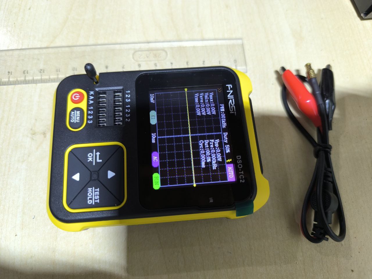
fNIRSi – something between an oscilloscope and a component tester.
Again, a Chinese product that boasts nothing on the packaging, probably only that it is a digital oscilloscope and transistor tester in one. Probably the most interesting thing you will see when you open the product packaging is the instruction manual, which is written in English in addition to Mandarin. In order to move on in this text I will list some technical data from the manual.
| Greatness | Range |
|---|---|
| Real-time sampling frequency | 2~MS/s |
| Frequency range | 0 - 200 kHz |
| Input resistance | 1~M\Omega |
| Input voltage range | probe 1 : 1 \;- \;80 V_{pp} (\pm 40~V) |
| Column 1 Value 5 | probe 10 : 1 \;- \;800 V_{pp} (\pm 400~V) |
| Vertical range | 10~mV/div; - \;10~V/div
range change after 1 – 2 – 5 |
| Vertical displacement | manually adjustable |
| Time base | 10~~mu s/div~ - ~500~s/div
range change after 1 – 2 – 5 |
| Trigger | Aut, Norm, Simgle |
| Trigger – slope | Leading and trailing edge |
| Trigger – level | manually adjustable |
| Screen freezing | Yes (HOLD function) |
| Automatic measurement | U_{MAX}, \; U_{MIN}, \; U_{AVR}, \; U_{RMS}, \; U_{PP}, \;f, \;T,\; Dcyc |
| PWM output | 0\;-\;80~kHz, Dcyc:\;0\;-\;100~\%,U_{AMP}=5~V |
For transistor tester parameters I prefer to help myself with pictures.
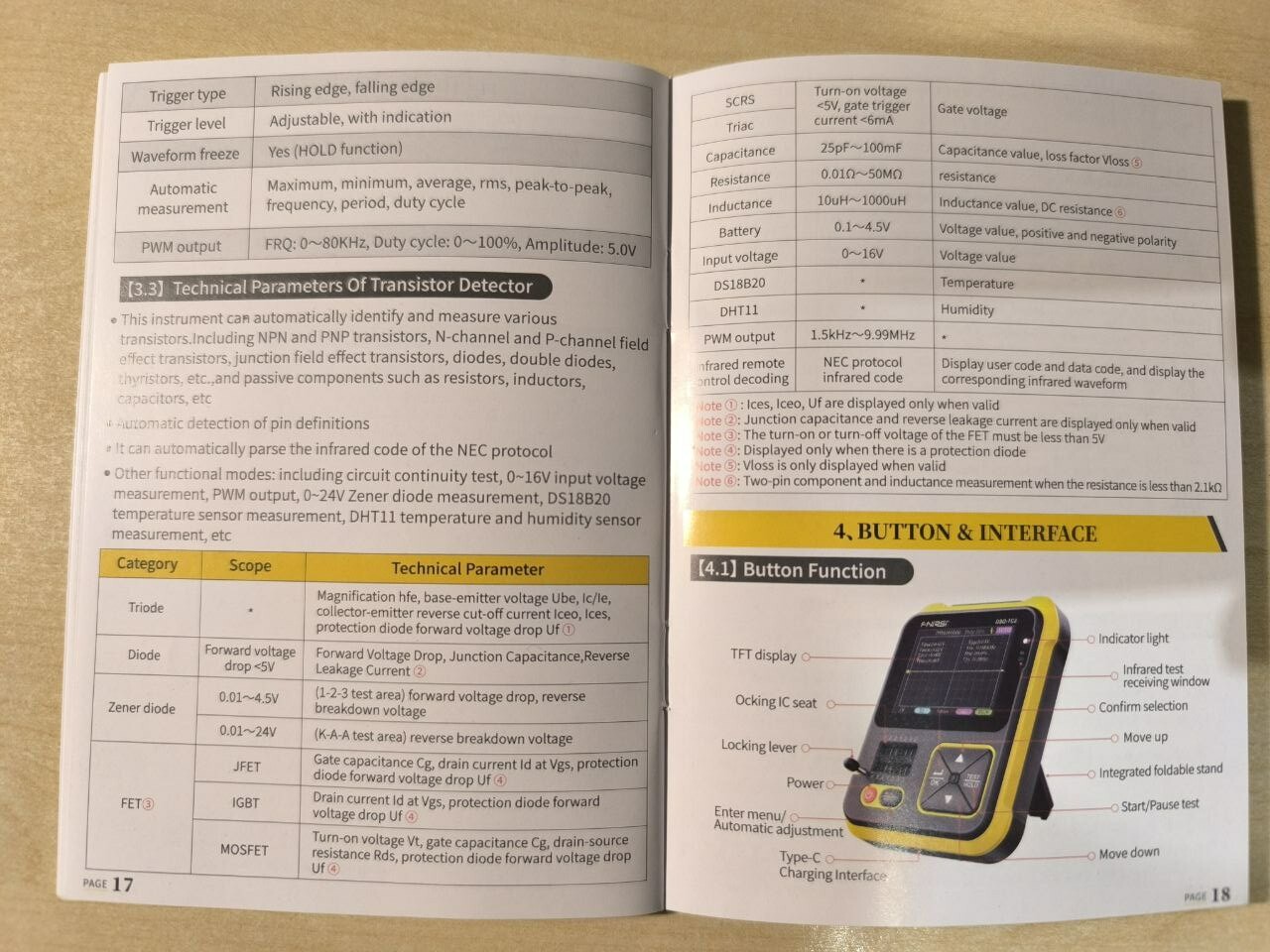
When the device is switched on, a menu consisting of two items appears on the screen: the Mos Test and the Oscilloscope. Use the arrow keys to select an item and press the OK button. If this item is Mos Test, the device will directly measure the parameters of the connected component. If none is connected the display will say unknown or damaged component. If we connect the component we have to press the Test button to make the measurement again. If we do nothing, the device will shut down after a while. This mode detects quite accurately the type of the component and its basic parameters (for a capacitor even the ESR, although I have no idea if it is the ESR or some loss at some frequency). For a bipolar transistor, the device even measures h_{21E}, and yet I don’t know at what operating point. And yet, this feature of the device is very useful for quick informative measurements of parameters of passive or active electronic elements. For example, it is invaluable in electronics or circuits exercises (when your course students run out of parts, or you need to quickly find a suitable transistor …). I recommend to try this mode (or similar, or this device). The DSO-TC2 as mentioned also has an oscilloscope function. We can select this one in the first menu. The display will show the oscilloscope screen in auto mode. This mode, the Chinese programmers understood literally. Everything is auto… synchronization, Y range, X range as well as turning on the measurement of the basic parameters of the displayed signal.
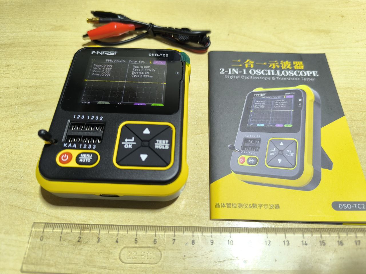
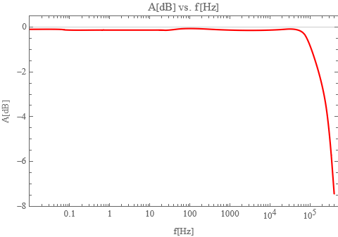
It is important to take a good look at how the oscilloscope is set up, as this determines the result of the measurement. My first measurement ended in a fiasco, the data was a strange characteristic of the oscilloscope, something more from quantum physics than from electronics … :D The oscilloscope needs to be calibrated . By long pressing the Menu button and not connecting the signal to the input, the problem with the strange data is solved – the oscilloscope is calibrated. For the next measurement, I don’t recommend to press the Menu button anymore, but to solve everything manually by pressing the OK button (each press brings up a different item on the display that can be manually adjusted) and the arrow keys. In this way we can set the trigger, slope, time base, input divider, input link and oscilloscope mode. The manufacturer declares an AFCH from 0 to 200kHz in DC mode. I was quite intrigued by that zero, so I tried to measure the AFCH using a TEKTRONIX oscilloscope from a frequency of 0.01Hz. The result is in the following picture.
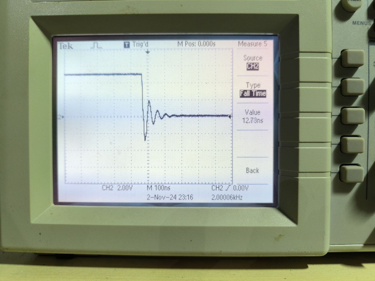
The DSO-TC2 has one more feature, a rectangular signal source whose frequency can be manually changed from the oscilloscope environment.The frequency of the signal can be changed from 0 kHz to 80 kHz and alternates from 0 to 100%. I have verified all these parameters. Both the frequency and the alternans matched to 3 decimal places with the TEKTRONIX calibration oscilloscope. The leading and trailing edge pulse lengths were 12.4 ns for all set frequencies. The following figure shows the waveform of the leading edge of the rectangular pulse.
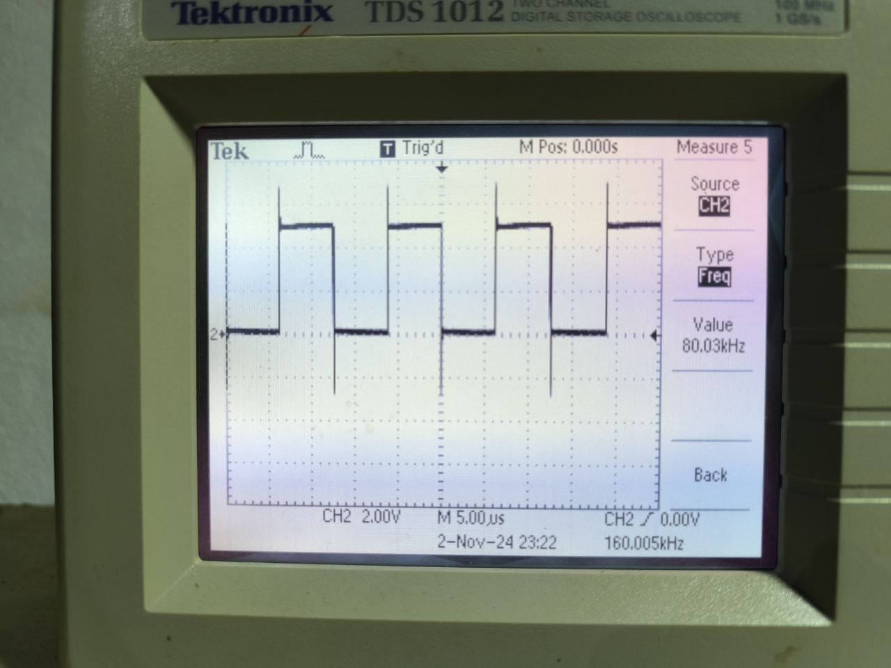
As the frequency of the rectangular pulse generator increased, the edge overshoot also increased. The highest overshoot was at the maximum frequency of 80 kHz. The overshoot was up to 3 V both above and below the 5 V pulse. Care must be taken when using this generator so as not to destroy the circuit to which the pulses will be applied.
Conclusion: The device – toy DSO-TC2, which I can refer to as a displayer and tester, is very useful in simple applications, such as laboratory exercises where one needs to construct a basic audio amplifier or switch, or even an RC generator. The specifications provided by the manufacturer are clearly met. The only disadvantage of the device is that it is easily portable in a pocket.
ZOSTANTE S NAMI

