
Project Description
-

-
Project Starting Date
1.04.2020
-
Project End
1.11.2020
-
Category
Research, development, production
Project Description
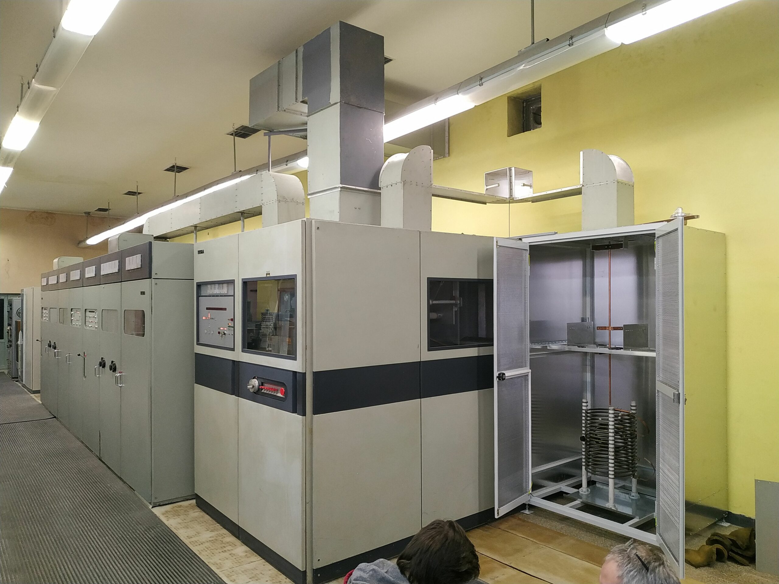
The task of the project was to design fabricate and commission an adaptation circuit – IMU from an unbalanced load of 250 Ohm to an unbalanced input of 50 Ohm. The problem was complicated by the fact that the circuit was to operate at a medium power of 25 kW, while this power, can exceed 33 kW.
If we convert the individual outputs into voltages, it is quite a demanding construction, which needs relatively large dimensions and correspondingly sized elements for electrical safety. Also, the design must take into account indirect lightning strikes or high induced voltages on the antenna system.
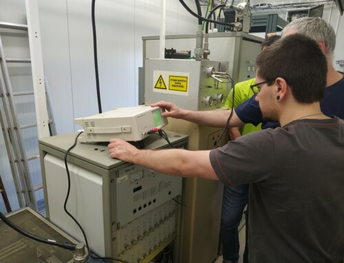
The Challenge in the design
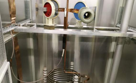
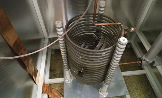
The IMU was conceived as a robust enclosure made of iron and aluminium in the centre of which the L-cell is symmetrically placed. The input and output of the IMU is on the top of the cabinet. The input is a square coaxial waveguide with flanges to minimize its radiation into the environment and the output is again a coaxial waveguide but circular with a professional 3 1/8” connector. The cabinet door is translucent and has a built-in switch that shuts off power from the transmitter when the IMU is opened. For the safety of personnel when servicing the antenna system equipment, power supply and transmitter, the IMU includes a shorting hook.
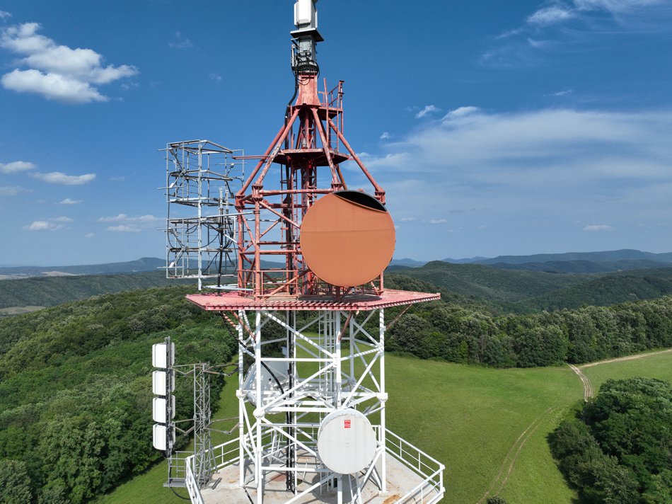
The IMU has been wired for fall 2020 as part of a mid-wave AM radio transmitter. To date, it has operated reliably without the need for maintenance intervention or completion of its parameters.
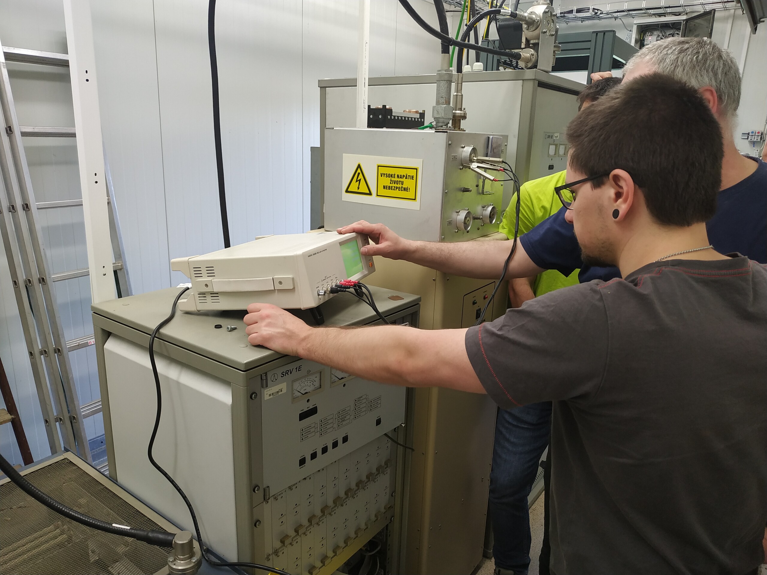
The Final Output
Features of the installed IMU
- Operating frequency 1098 kHz
- Impedance on the power supply side 250 Ohm
- Impedance on transmitter side 50 Ohm
- PSV (VSWR) = 1,05
-

